YD1JJJ RF SPEECH PROCESSOR
 29-aug-2016

YD1JJJ's original design.
INTRODUCTION
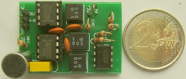
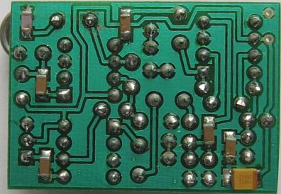
Miniature 5 × 5 cm PCB, good quality and components properly installed.
On eBay I discovered an ad of an outboard RF speech processor designed by YD1JJJ. It was originally a kit for DIY, but this PCB was assembled and tested.
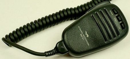
The Rf clipper is intended for mounting into a (fig») MH-31 microphone for FT-817, FT-857 and FT/ND-89 transceivers, but in my opinion it can also be used otherwise.
Because of the simple circuit, low price and my experience with RF or DSB clippers, I was curious how it would work in practice. Therefore it was ordered and the total cost including shipping from Indonesia were about 24.72 EURO. That can't be a bad buy!
It turned out to be good quality PCB with properly installed components, that can be seen on the pictures above. The accompanying documentation was only in Malay.
IN PRACTICE
In practice, the gain was far too much resulting in sharp modulation peaks and pretty annoying background noise.
|

NE592 = SA592 = SE592 ~ µA733
|
Apparently too much signal from the microphone because the input of a NE602 can be overloaded fairly quickly. The modification was held simply to avoid damage of the tiny PCB.
The microphone was extra loaded with a 1k0 resistor mounted across pins 1 and 2 of the first NE602A.
At the delivered speech processor pins 2 of of both NE602A's were not decoupled with 100 nF. I decoupled the first IC because a floating input can pick up all kinds of unwanted signals and is sensitive for RF feedback!
Which I have been afraid of was also happened: the electret microphone was suffering from RF feedback. Instead of the much applied decoupling with a 1 nF capacitor, I did it with 10 nF. Audiophiles will have their doubts with this value, but my experience is that with ham SSB it works and RF is decoupled more effective. In this circuit the microphone is loaded with 600 Ohm (1k0//1k5) and 10 nF relative to 1 nF makes little difference in terms of audio.
The clipping diodes were equipped with an extra 10 kOhm series resistance and as bonus one gets a logarithmic clipping with less distortion.
Because the microphone gain of my FT-890 is very large, a resistor was mounted between speech clipper and microphone input.
The 9 V supply voltage is reduced by an 68 Ohm resistance in series with the positive terminal of the battery.
Due to all changes all reports are: loud speech but sounds good, however further developments are not impossible.
INSTALLING MICROPHONE CASING
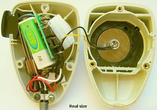
Because the audio speech processor of my YAESU FT-890 is not really great, the goal was to test YD1JJJ's design with this set and to merge "in a moment" the PCB with a microphone in his enclosure.
A relatively small FT-890 is so densely populated with components, that there is almost no room for an extra PCB or components.
The "in a moment" did not work because all 8 pins of the microphone input were occupied, so that without heavy labor an additional DC voltage from the set was not easy to obtain.
Supply and clipper had to fit together in the microphone casing. Luckily after some messing it was possible to join both in («fig) a MOTOROLA type.
If the dual microphone switch is turned on at first the 9 Volt battery is connected and in sequence PTT is activated.
A floating microphone in an enclosure is usually asking for misery, because the sound is adversely affected by the echo of the space. Therefore, the electret was mounted in a front panel, so that the voice only ends up into the microphone.
ADJUSTMENT
The problem with speech processors is that many hams want to have the extreme, so that it sounds unpleasant for the receiver. The goal is in fact strived beyond. Less clipping is the cure. Adjusting using a scoop is fine, but without can also be done.
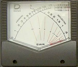
If one speaks normally into the microphone with a 100 W transmitter, the needle of a mechanical PWR-meter (not PEP mode) shows an average 10 W.
In the CW mode and with quick points the meter shows an average 30 W. With heavy clipping one can push the meter also for an avarage 30 W, but that is to much.
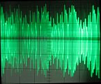
Better is to decrease the clipping for an average of 20 W. Often one don't notice that an processor is active, while the average ouput is increased significantly. I estimated about 3 dB.
Adjust Mike Gain of the set as follows: whistle into the microphone and increase the gain for maximum (100 W) output. Then reduce for an output of about 90 à 95 W. How load you speaks into the microphone, the output stage of the set can not be overmodulated and ALC remains moderate.
CONCLUSION
YD1JJJ has designed a striking and simple processor. The small size is due to his search for the smallest possible filter: MURATA CFUM455G!
The speech clipper, you may have to modify a little, works very effectively. An example: the fan of my FT-890 starts much earlier: an indication that average ouput (fig») increased.
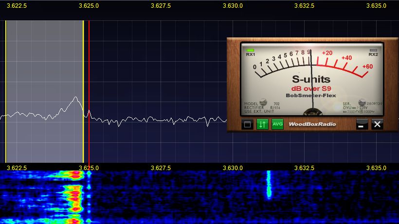
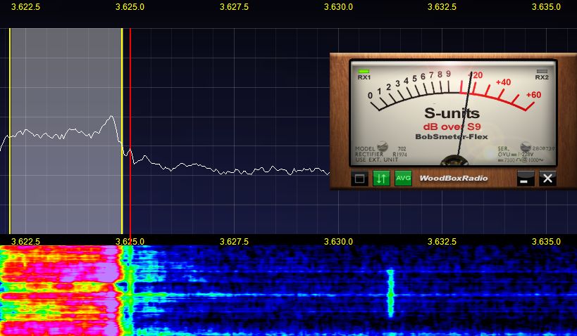
The recording was made with FlexRadio 5000
Without processor with original MH-1B8 dynamic microphone and average 10 W SSB output.
With processor and electret microphone. Due to clipping an average of 30 W SSB ouput.
The S-meter shows increase in average power. The waterfall also indicates that the signal is better "filled".
Both recordings are done almost immediately after each other by fast swap of the microphones, so that a comparison of the outcome is almost 100% sure. Because the S-meter of a FlexRadio 5000 is pretty accurate, one can see that by applying the processor the (averagel) ouput has at least quadrupled.


![]() 29-aug-2016
29-aug-2016





![]()